![]()

where d and A are the thickness and cross-sectional area of the material, respectively. The resistivity, an intrinsic property of the material of which the resistor is composed, is large for good insulators and small for good conductors (Table 1).
|
Table 1: Resistivity of Conductors and Insulators |
|||
|
Material |
Resistivity at 0 oC ( |
Resistivity at 22 oC ( |
Classification |
|
Silver |
1.47 |
1.61 |
Conductor |
|
Copper |
1.55 |
1.70 |
Conductor |
|
Gold |
2.05 |
2.20 |
Conductor |
|
Aluminum |
2.50 |
2.74 |
Conductor |
|
Ceramic (Porcelain) |
- |
1018-1020 |
Insulator |
|
Plastic (Acrylic) |
- |
>1021 |
Insulator |
Combinations of Resistors:
When n resistors are connected in series (end to end), the
equivalent resistance, Req, of the series combination of
resistors is the sum of the individual resistances such that ![]() where Ri is the
resistance of the ith resistor. (Note: Elements in series
have the same current through them.)
where Ri is the
resistance of the ith resistor. (Note: Elements in series
have the same current through them.)

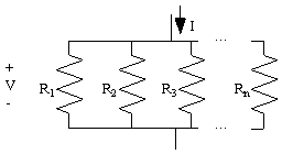
When n
resistors are connected in parallel, the equivalent resistance,
Req, of the parallel combination of resistors is the sum of
the individual resistances such that  where Ri is the resistance of the ith
resistor. (Note: Elements in parallel have the same voltage across
them.)

Resistor Color Code Description:
http://www.eg.bucknell.edu/~bsprunt/classes/references/resistor_color_codes/resistor_color_codes.htm
Resistor Code Calculator:
http://www.eg.bucknell.edu/~bsprunt/classes/references/resistor_values/resistor.htm
Study the circuit below. It has five resistors: R1, R2, R3, R4, R5 and four switches S1, S2, S3, S4. These switches can be opened and closed to control the current i. In a more advanced system, a computer could be used to turn on and off various switches in sequence to control the current in the circuit.
** WE WILL NOT USE ACTUAL SWITCHES; JUST USE WIRES TO CLOSE SWITCHES. **

Record your calculations and circuits in your lab notebook. Also, record the resistor values and the switch settings required to obtain each of the desired currents in your lab notebook.
Measure the resistance of the circuit that you designed for each of the switch settings using the ohmmeter setting on the DMM.
You do not have to connect the 5 V source or measure current. Please measure the equivalent resistance of your network for various switch settings, and use Ohm's Law to determine the current that would result with a 5 V source.
Thank you.