Pre-Lab Exercise: Analyze each circuit in Lab 8 and determine formulas for the frequency response. Include the analytical frequency response curve on your Bode plots with the experimental data, and include the plots in your lab notebook. Comment on the agreement between the theoretical and experimental frequency responses. What are the cutoff frequencies for each filter?
Problem: Design and construct a three-band equalizer circuit. Your circuit should include three filters: a low-pass filter that passes frequencies up to about 500 Hz, a band-pass filter that passes frequencies centered around 1073 Hz, and a high-pass filter that passes frequencies above about 2000 Hz. You should be able to adjust the gain (or amplification) of each frequency band independently. You will demonstrate the operation of your equalizer by passing music through your circuit and playing the "equalized" music through a speaker.
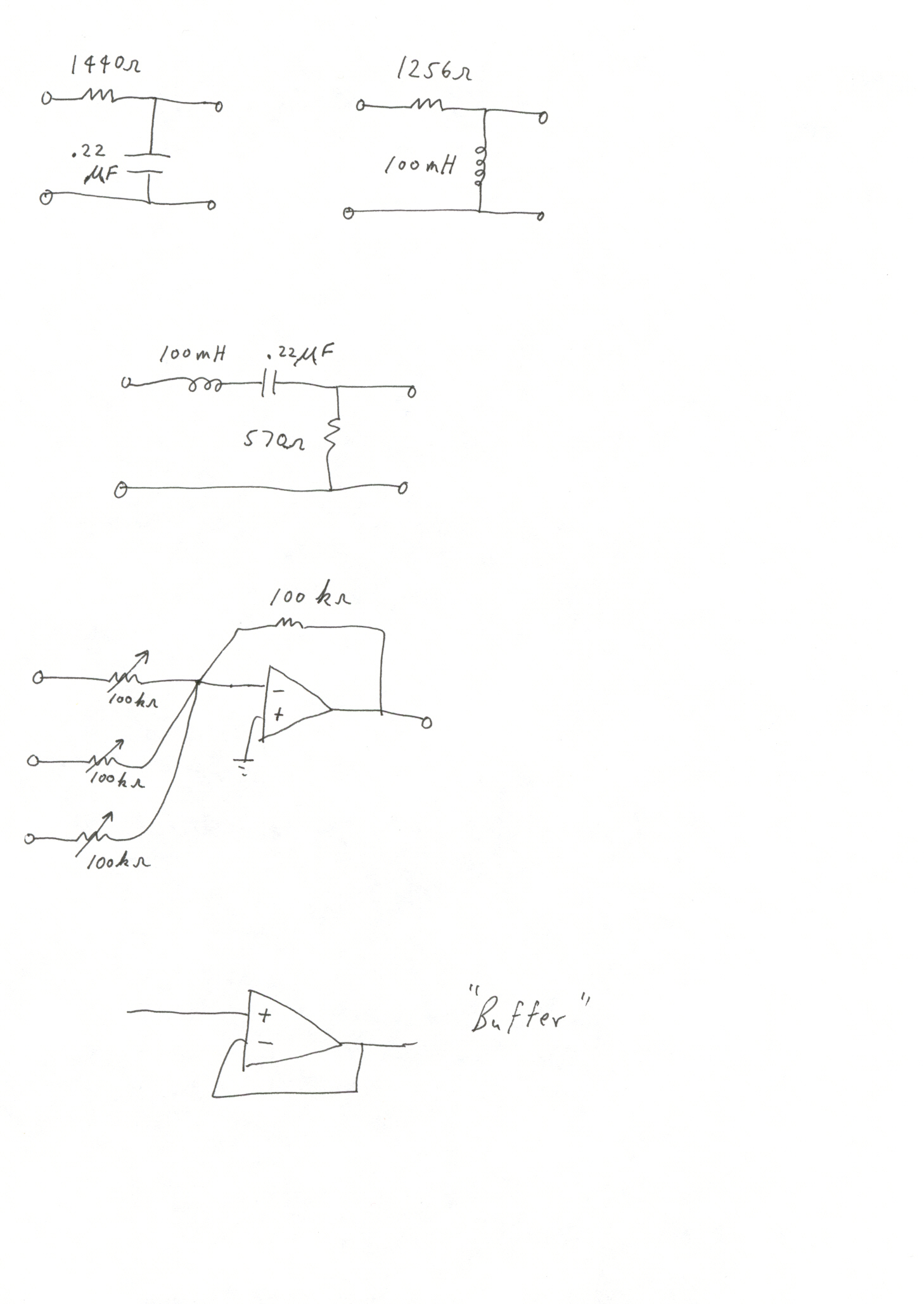
System Design: Use the "subsystem" circuits shown below to design your equalizer. Which circuit is the low-pass, band-pass, and high-pass filter? What is the "cutoff" frequency of each filter? How should you connect the subsystems to form your equalizer? Do you need "buffer" circuits in your design?
Procedure: