Introduction
Electrical and computer engineering come together in the design, implementation and testing of digital electronics. Digital circuits form the basis for computers, peripheral devices, process controllers and many other devices.
Digital circuits are based on Boolean algebra. In fact, digital electronic components are simply a realization of Boolean algebra functions. A digital circuit constructed by connecting the outputs of digital components to the inputs of other digital components is an implementation of a Boolean function.
In this lab, you will investigate the use of digital electronics in the control of an alarm buzzer in an automobile. Your circuit will use digital signals from sensors that detect when a door is open or the motor is running to determine when to sound the alarm.
The design of a digital circuit involves multiple steps. First, you will develop a written description of the operation of your circuit. Next, you’ll use a simulation program called LogicWorks to model your circuit. Simulations are often used to test circuit designs because (as you will discover) it’s typically much easier to draw the circuit on a computer than it is to build the circuit out of hardware and wires.
In this lab, you will first simulate your circuit design to verify that it is correct, and then you will implement your circuit in hardware and confirm that it functions correctly.
The problem
Design and construct a simulation for a digital circuit to control an alarm buzzer in a car. The alarm will warn about driving without buckling seatbelts, leaving the key in the ignition or leaving the lights on. Here is a more detailed description of the operation of your circuit:
The alarm is to sound if the key is in the ignition when the door is open and the engine is not running, or if the lights are on when the key is not in the ignition, or if the driver’s seatbelt is not fastened when the motor is running.
Input and output devices
To construct your digital circuit, assume you have five sensors that generate digital signals:
|
Signal name |
Sensor |
If signal = 1 |
If signal = 0 |
|
K |
key |
Key in ignition |
Key not in ignition |
|
D |
door |
Door open |
Door closed |
|
M |
motor |
Motor running |
Motor not running |
|
L |
lights |
Lights on |
Lights off |
|
B |
seatbelt |
Belt buckled |
Belt not buckled |
Materials
To complete the implementation of your digital circuit, use:
Design specifications
Procedure
Record the work from each step below for inclusion in your lab notebook.
Hardware implementation and layout
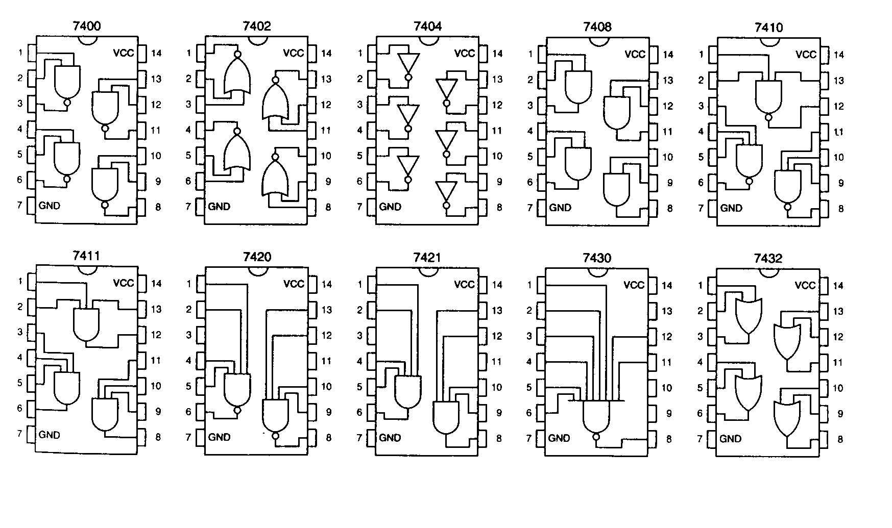
Decide which integrated circuits (ICs) or "chips" from Figure 1 you will use to implement your circuit. Note that a three-input OR gate is not available.
There is an obvious implementation that uses 4 ICs. Please find a more efficient implementation that uses only 3 ICs. Also, use NAND gates to find an implementation that uses only 2 ICs. We will simulate and implement the 2 IC solution.
How to wire an LED
The output of your logic circuit will be an LED, even though your description stated that a buzzer would sound. An LED is used because it is much easier to wire than the circuitry associated with a buzzer. An LED passes current in only one direction, so if it does not light for a logic "1", just turn it around. The resistor is needed to limit the amount of current that flows through the LED and the integrated circuit (IC) chip.
Figure 2. LED Connection
Wiring procedure
Results to include in lab notebook
Your Boolean expression for the design, logic circuit diagrams that corresponds to your Boolean expression, the truth table, a printout of your LogicWorks simulation, and your layout/wiring diagram for the design that uses two ICs and NAND gates.