We have several objectives in lab this week. Some of the things we will do include:
Designing a Voltage Divider Sensor
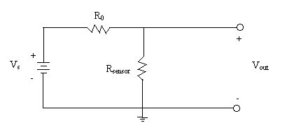
Voltage divider circuits are often used in measurement instruments to convert a physical quantity such as light intensity, temperature, or elastic strain into a voltage. An example circuit is shown below.
A material that changes its resistance in accordance with light is called a photoresistor, and a material that changes its resistance in accordance with temperature is called a thermistor. The resistor Rsensor in the above circuit represents such a device. Voltage dividers are also used for things like volume controls on radios and televisions, dimmer switches on lights, and intensity controls on computer screens. In these applications, the resistance of a potentiometer (or "pot" for short) is varied by the user to change the output voltage.
The above circuit produces an output voltage Vout that lies between the source voltage and ground. In your lab notebook, please derive the relationship between the output voltage and the source voltage, as determined by the resistance values. (You should have done this exercise before, but make sure you understand it.) Note that Vout will vary with the physical variable that we are measuring as Rsensor changes.
Please answer the following questions in your lab notebook.
Sometimes the sensor is exposed to only two values of the physical variable, and an instrument must distinguish between the two levels. For example, a light might shine or not shine on a photoresistor. Then we might want to design the circuit in order to obtain the largest difference between the two voltages produced. If the supply voltage Vs is 5 volts, and if we can make the output voltage close to 5 volts and 0 volts in the two conditions, then we have designed a circuit that produces levels close to the standard levels in digital logic. Determine the resistance R0 that gives the greatest difference between the output voltages when Rsensor = Rmax and Rsensor = Rmin. Then determine the maximum difference, and how close you can get to 0 and 5 volts.
During the lab period, be sure that you understand how to set up this analysis and the approach used to find the best value for R0. You may want to finish the steps in the analysis after the lab session.
Consider an application of your result. Suppose that you have a sensor for which the resistance varies between Rmin = 1000 ohms and Rmax = 5000 ohms for two fixed conditions. In digital logic circuits, anything above 3.5 volts is sensed as logical "1", and anything below 1.5 volts is sensed as logical "0". However, the more you exceed these limits, the more reliable the circuit will be. For the sensor described above, can you achieve reliable operation? We will check your prediction later in the lab by building the circuit.
Testing the Voltage Divider Circuits
Next we will construct some voltage divider circuits in order to test the results from previous sections. First let Vs = 5 volts and replace Rsensor by a resistance value of 1000 ohms. Next replace Rsensor by resistance value of 5000 ohms. Choose R0 to achieve maximum voltage difference for the two values of Rsensor. Measure the actual voltage levels for the two cases, and compare with your earlier predictions.
Second, we will use a thermistor as Rsensor. Measure the resistance of the thermistor at room temperature, and when you heat it by squeezing between your fingers. Choose a value for R0, and set up the voltage divider circuit. What values of Vout correspond to room temperature and body temperature? What would happen to your measurements if the source Vs deviated from 5 volts?
Bridge Circuits
Let us consider a bridge circuit, which is shown below. The bridge circuit is really just two voltage dividers, and it has some practical advantages over a simple voltage divider.
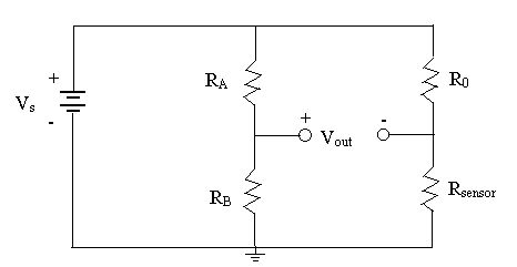
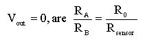
In this bridge, the output voltage Vout is now a difference between the two sides of the bridge. If the circuit components are chosen properly, the voltage difference will be zero. Show the conditions for a "balanced bridge,"
Please do the following exercises with the bridge circuit.
E-Lessons
A number of interesting E-Lessons are available on voltage dividers and bridge circuits. Feel free to browse them whenever you would like. The path to the E-Lessons is described in Lab 2, and the voltage divider lessons are under "Elements -> Resistors -> Voltage Dividers".