ELEC 101, Spring 2005
Prof. Rich Kozick
Laboratory 4
Operational Amplifier Introduction
The objective in lab this week is to get an introduction
to operational amplifiers (op amps).
We will discuss op amps in lecture next week, and then we will
do some more interesting applications of op amps in
Lab 5.
1. Electronic Lessons on Op Amps
Please read through the
E-lessons on op amps at
http://www.facstaff.bucknell.edu/mastascu/eLessonsHTML/EEIndex.html
The op amp lessons are located under the Elements item, and
you should read through the first two lessons, called
Op-Amps-General and
Op-Amps Inverter.
Use the lessons to guide you through setting up the inverting
amplifier circuit in Section 2.
You should read through the analysis in the E-lesson, but we will
discuss op amps in detail during lecture next week.
2. Inverting Amplifier
Consider the inverting amplifier circuit shown in Figure 2.15
on page 75 of the Bobrow text.
- Repeat the analysis that leads to the result that the
output voltage vo is related to the input voltage
vs according to
vo = -(R2 / R1) vs.
For your convenience, the inverting amplifier circuit shown in Figure
2.15 of the Bobrow text is shown in Figure 1 below.
The notation in Figure 1 is slightly different from the text, so
the equation describing Figure 1 is
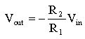 .
.
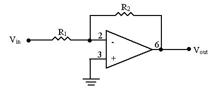
Figure 1: "Inverting amplifier" with 741 op amp.
- Build an inverting amplifier with
gain = -(R2 / R1) = -10, using
R1 = 1 k ohm,
R2 = 10 k ohm.
You can obtain the pin diagram for the 741 op amp from the
data sheet on the course web page under
Laboratories,
or you can refer to Figure 2 below.
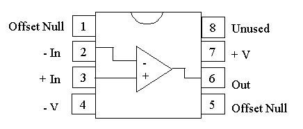
Figure 2: Pin diagram for 741 op amp.
The pin numbers are also indicated in the circuit in
Figure 1 above.
We will use "supply" voltages +V and -V in Figure 2
equal to +12 volts and -12 volts, respectively.
- If you have time, try modifying your circuit to achieve
"gains" of vo / vs = -1 and -2.
For each case, measure the output voltage vo for several
positive and negative input voltages vs.
Are there any limitations to these circuits?
In other words, are there circumstances under which the
desired gain is not achieved?
What is the largest output voltage that your circuit can achieve?
Can you explain why?
- Suppose you want to design an inverting amplifier with
a variable gain using a potentiometer (pot) whose resistance
varies from a few ohms to 10 k ohms as a dial is turned.
(This might be used for a volume control in a radio.)
Should the pot be placed at R1 or R2?
Try putting the pot in your amplifier circuit, if you have time.
Record information in your lab notebook that will help you in future
weeks when construcing op amp circuits.
Also, keep your inverting amplifier wired on your breadboard and we
will use it next week in
Lab 5.
Thank you and have fun!