Prof. Kelley's Home Page
Research Topics |
Ice-Penetrating Radar AntennasThis project involved the development of an antenna for use with an ice-penetrating radar (IPR) system. The work was sponsored by Dr. Sridhar Anandakrishnan of the Penn State University Department of Geosciences, who has been using the IPR system to study glaciers in Antarctica. Another collaborator on the project was consultant Dr. Bruce Long, who designed and built the transmit, receive, and control systems. The development effort focused on designing and building a tunable bowtie antenna for use at a center frequency of 50 MHz. One of the primary challenges was to design an antenna that would operate over ice with varying degrees of porosity. The project goals included:
Bucknell Student Contributor
Final Version of the IPR AntennaA photo of the antenna is shown below. The substrate for the antenna is formed by two 1.5-inch thick by 48-inch square pieces of high-density polyethylene (HDPE). The front piece is attached to an aluminum "prow" that helps the antenna ride over ice boulders and rough glacial surfaces as it is dragged behind a vehicle. The weight of the HDPE pieces helps to keep the antenna flush with the surface. The towing bridle is connected to an aluminum rod that passes through the prow. A thin sheet of flexible low-density polyethylene (LDPE) is attached to the prow and lies underneath the thick HDPE sections. Its purpose is to present a low-friction surface to the ice and to prevent snow from encroaching through the seam between the two HDPE pieces. The small table above the center of the antenna holds the transmit/receive module, and the LDPE rod attached to the prow supports the control and data cables that run between the antenna and the tow vehicle. The antenna is tuned in the field by swapping out the variously sized aluminum extensions on the ends of the bowtie. The photo shows all of the extension pieces on the antenna, but in practice only one piece on each end would be used at a time. The extension pieces have slots that mate with two captive bolts on the ends of the permanent alumimum pieces (the two large aluminum triangles). Wing nuts hold the extension pieces in place. Not shown in the photo is a small variable capacitor mounted in a protective box that can be attached in series with the feed point of the antenna. Its purpose is to tune out the inductive input reactance. 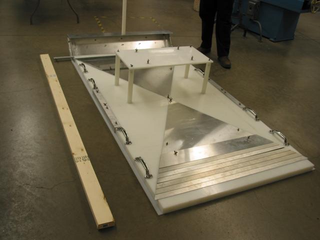
|