NODE ARCHITECTURE
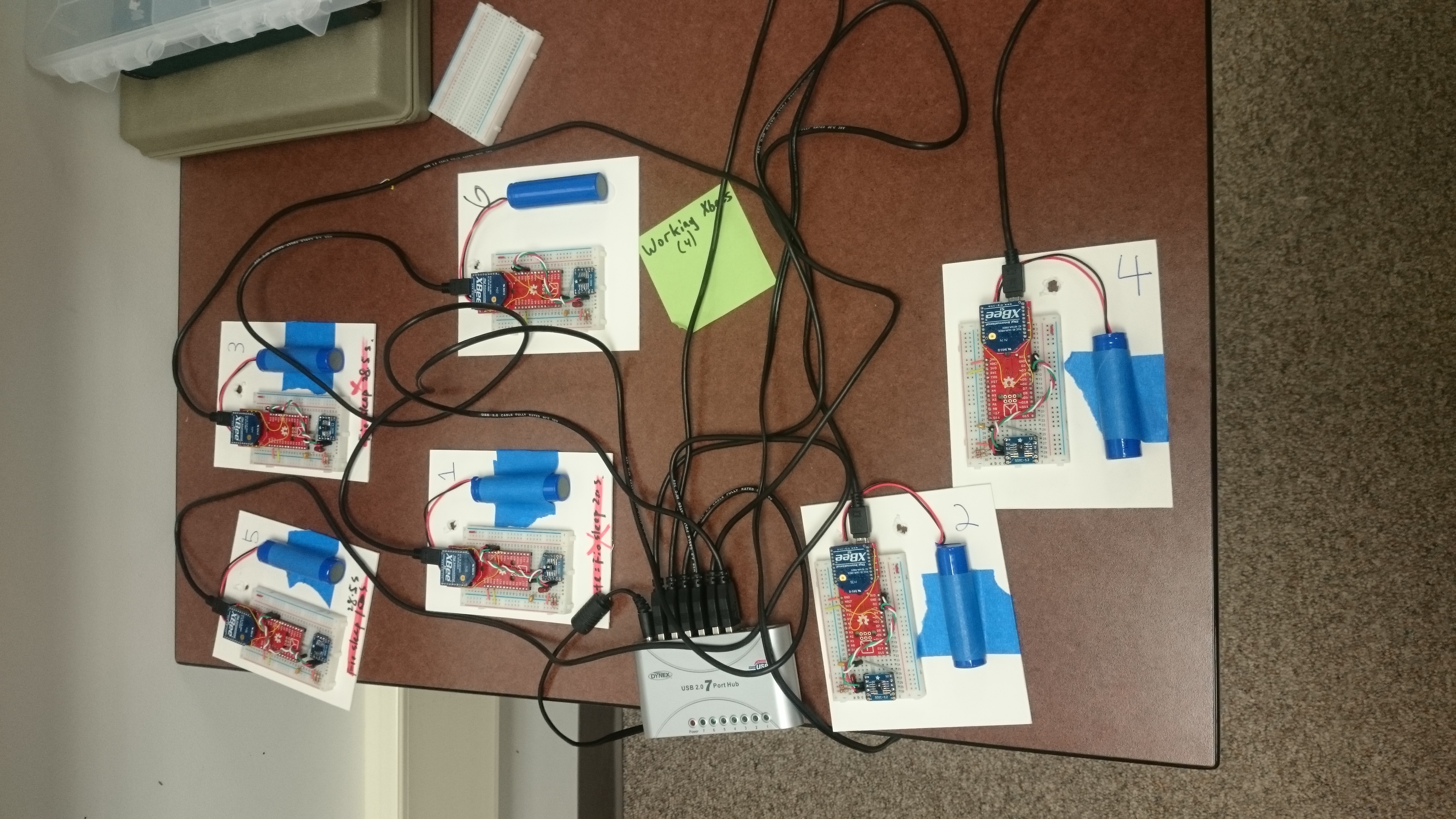
Each node is equipped with honeywell temperature and humidity sensors wired to an arduino-compatible computer chip. Each node also contains an xbee radio for wireless communication and a 3.7V lithium ion battery power source. Nodes are spread throughout the storeroom of the Samek Art Museum.
Before we deploy all the nodes, they are charged by a power station, shown below.
LOW-POWER LISTENING
Since our nodes will be using battery as the primary power source, our system is relatively sensitive to energy constraints. Furthermore, we want to collect data for a relatively long period of time. The microprocessor in Fio V3 and the Xbee radio consumes quite a lot of energy, even while they are idling. We need to put both Xbee and Fio V3 to sleep in the intermittent time interval.
The overall sensing cycle is defined as following:
Begin ➜ Fio MCU On ➜ Sample ➜ XBee On ➜ Tx ➜ XBee Sleep ➜ Fio Sleep ➜ Repeat
XBee Radio Sleep Mode
Sleep mode enable the RF module to enter states of low-power consumption when not in use. Sleep mode setting (SM) should be 1: pin hibernate mode. After assert (high) Sleep_RQ (pin 9), XBee will enter sleep mode. To wake up XBee, just de-assert (low) Sleep_RQ. XBee will take <10 uA in sleeping mode and the wake-up time is 13.2 msec. When XBee is in pin sleep, the module will not respond to either serial or RF activity.
Fio v3 MCU Sleep Mode
Narcoleptic is a library to reduce the power consumption of Fio. It uses the sleep functionality of the AVR microcontroller to shut down the entire CPU. However, it won’t be able to shut down the LED on Fio. Therefore, we took all the resistors connecting to the LED’s on the Fio board by hand except TX LED. The TX LED will be shut down by Arduino code at deployment.
Implementation
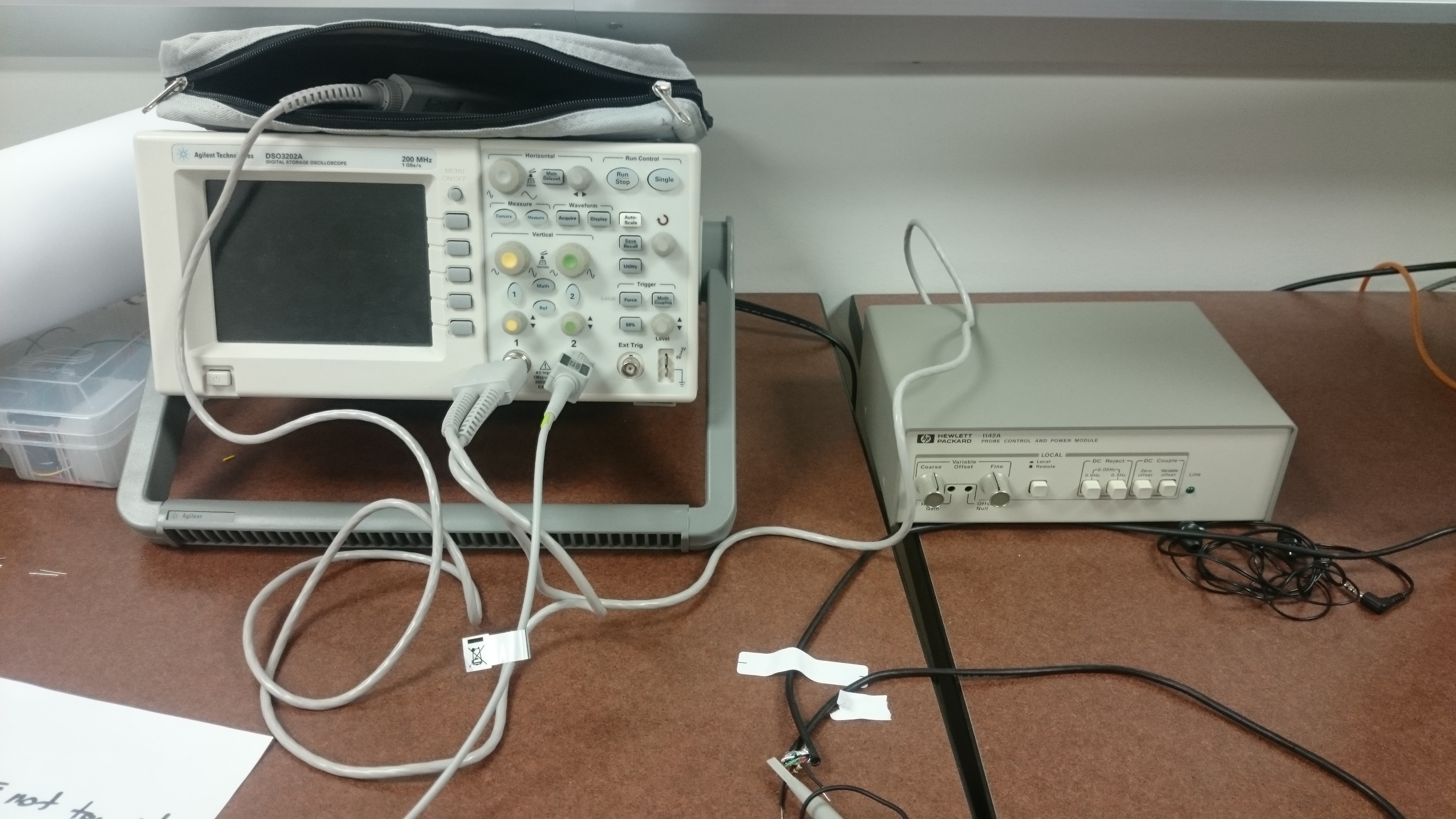
In order to validate that our sensors are truly in the sleeping mode, we need to find a way to measure the current consumption for each sensor. We used oscilloscope with differentiate probe to measure the current through Fio board, shown below:
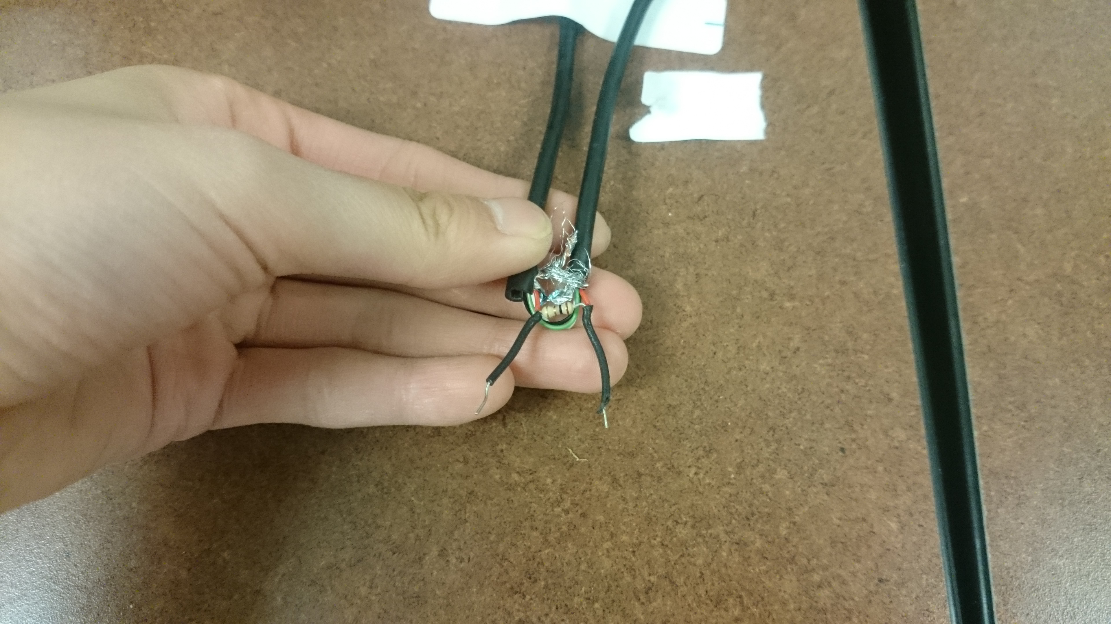
Professor Marchiori prepared these devices, along with a special cord to us. He cut the micro-USB cord and attached a 1 ohm resistor to it. In this way, the voltage across this resistor will be the current through our system. The cord is shown below:

Recent Comments